
How to achieve multi-filament 3D printing and make it fully automatic?…

During my second year of study at the University of Toronto as a Mechanical Engineering undergraduate student, our MIE 243 (Mechanical Engineering Design) had a course project which was to design a 3D printer benchmarking the Banboo X1 Carbon high-speed 3d printer. Even though it was just a conceptual design, it was still a huge challenge as it still had to be functional as a huge assembly with over 200 parts.
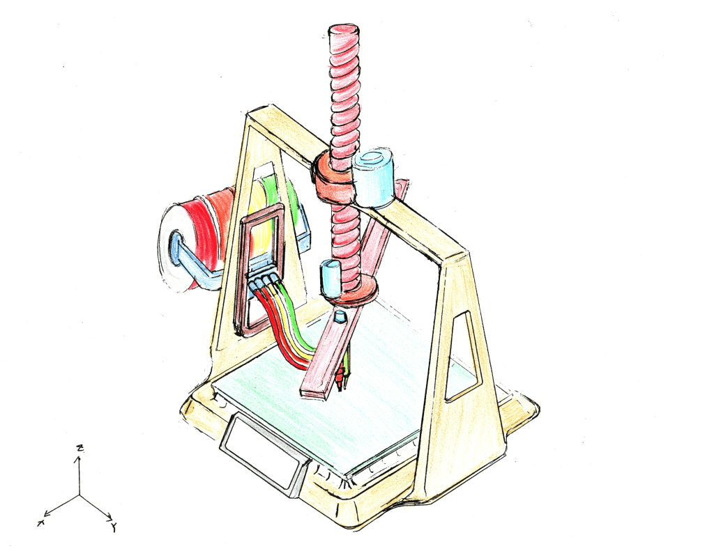
Here are the candidate design drawings (r-theta & 5-axis 3d printer) I drew. Finished in 30 minutes to show the general ideas which were also used later for the selection of design using a decision matrix.
The key objectives include cost, speed, ease of use (simplicity), and multiple filament feeding features. The final decision was to design a 3-axis printer instead of the previous 2 designs mainly due to the cost and simplicity objectives.
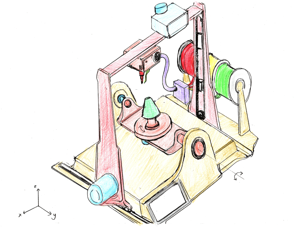
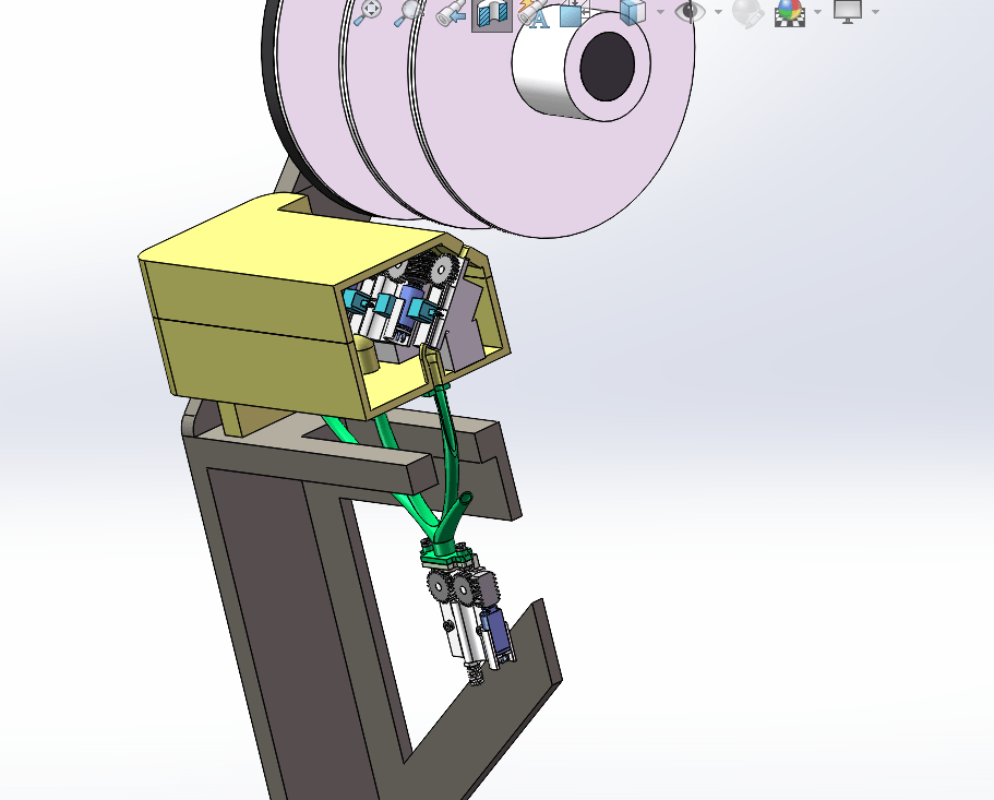
Specifically in this project, I designed the multi-filament automatic feeding system (shown below) which is able to take 4 types of different materials (or the same material but different in color) and change filament automatically.

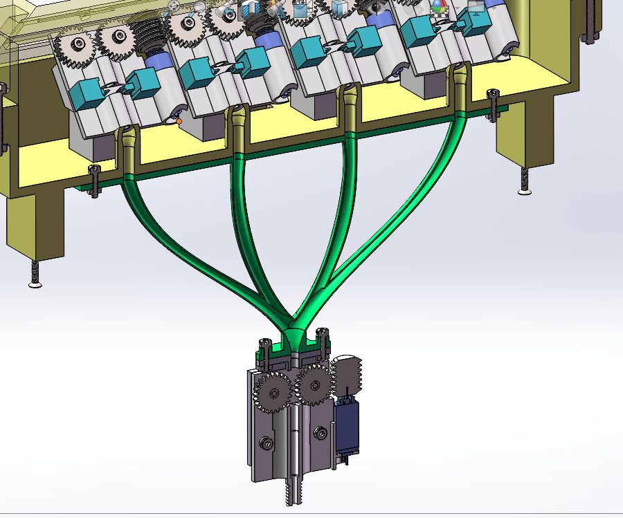
The system mainly consists of 4 parts: spools, a feeding box (with 4 extruding units), a branch guiding tube (the green tube), a main extruder (under the branch guiding tube), and the supporting structure. The idea was to feed four different filaments individually but still integrate everything together as one system.
All the spools are mounted on the spool rack preventing horizontal displacement to align filaments better. The spools and the rack are both locked by rotating in different directions.

Starting with the spools of filaments. As the pictures showing below, each filament spool will go through one extruding unit and run through the branch guiding tube. However, all four filaments will merge into one tube and only one will be extruded by the main extruder which will then send the filament to the print head.

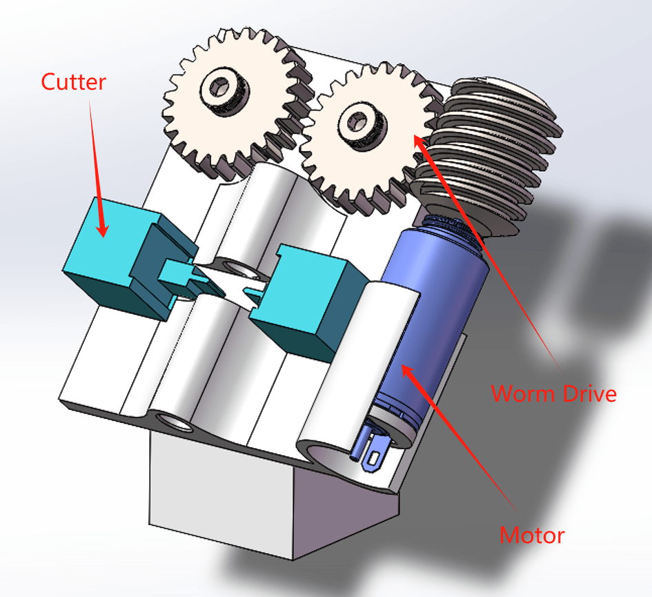
The feeding unit has a worm drive which ensures that the output angular velocity is much smaller than the input motor’s angular velocity (RPM). Based on the printing speed, we set a range of feeding speeds to design/select suitable gears for the extruding units. The cutter will cut the filament to prevent the rest of the filament from going after the filament switch. The cutter has a heated blade which will easily cut through the material. The cutter will cut the material only after the filament gets caught by the main extruder which is located at the end of the branch guiding tube to guarantee the cutted filament keeps moving towards the print head.
However, this was not the best design compared to the retraction method which is commonly used in most printers. By using retraction, the whole system would be more simplified and easy to control.
In our conceptual design, there would be built-in functions for controlling the 4 individual extruding units. Since this was out of the course scope, we only assumed the function had already existed. Specifically, each individual extruding unit will be controlled for when to extrude and cut the filament to achieve seamless filament change. The motor control will be based on the length of the filament which has already been extruded, and this can be measured from the gear’s rotation which is feasible.
