Can I design a fixed-wing myself from scratch and make it fly? …
Among all my passions, there is a special one. It is fixed-wing remote-controlled (RC) planes design. I started my exploration in aircraft when I was 11 and really started my RC journey at middle school making home made RC planes.
After going into the university, I really learned a lot about engineering designs, analysis, and many other important technical knowledge behind the designs. I asked myself, can I challenge myself to design, build, and fly an RC plane all by myself?
With this passion, I started…
I am a big fan of mid-20th-century aircraft (low-wing tail draggers with propellers). Therefore the goal is to design a single-seat low-wing tail dragger with one propeller.
Design
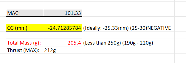
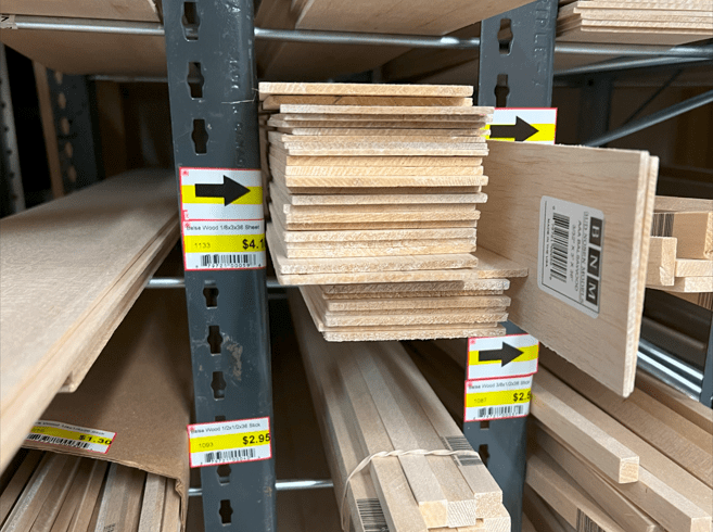
Feasibility and some key dimensions (e.g. wingspan and weight) were determined first. Because of the price of balsa wood and the ease of storage, I aimed to design a small wingspan fixed-wing. In addition, the restrictions applied to any drones that weigh more than 250 g in Ontario, Canada are much harsher than the ones below that weight limit which are classified as “micro-drone”. After checking all of the restrictions, primary objectives, and available electronics, I decided to move on with the “550 mm wingspan with detachable wing and 2s Lipo battery with 1806 brushless motor” design.
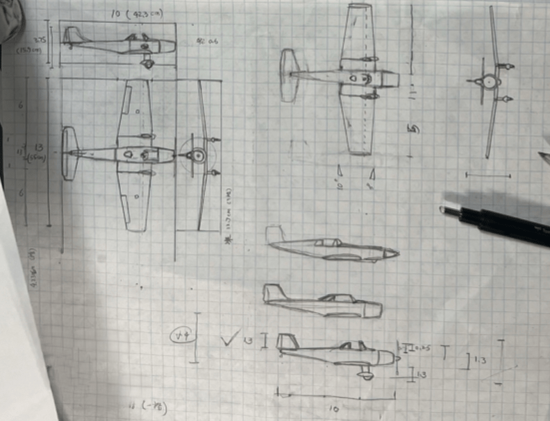
The design started with some simple sketches on paper … I evaluated a few combinations and then picked this design layout (it was the most feasible idea for my first balsa wood plane design). Then, the sizing and basic design layout of the plane were done right after this. I referenced some design sizing of the existing planes and some design guidelines. Later, the layout design was enlarged to make it easier to see and have more detail (I made a reference ruler to help with scaling up the sketch).

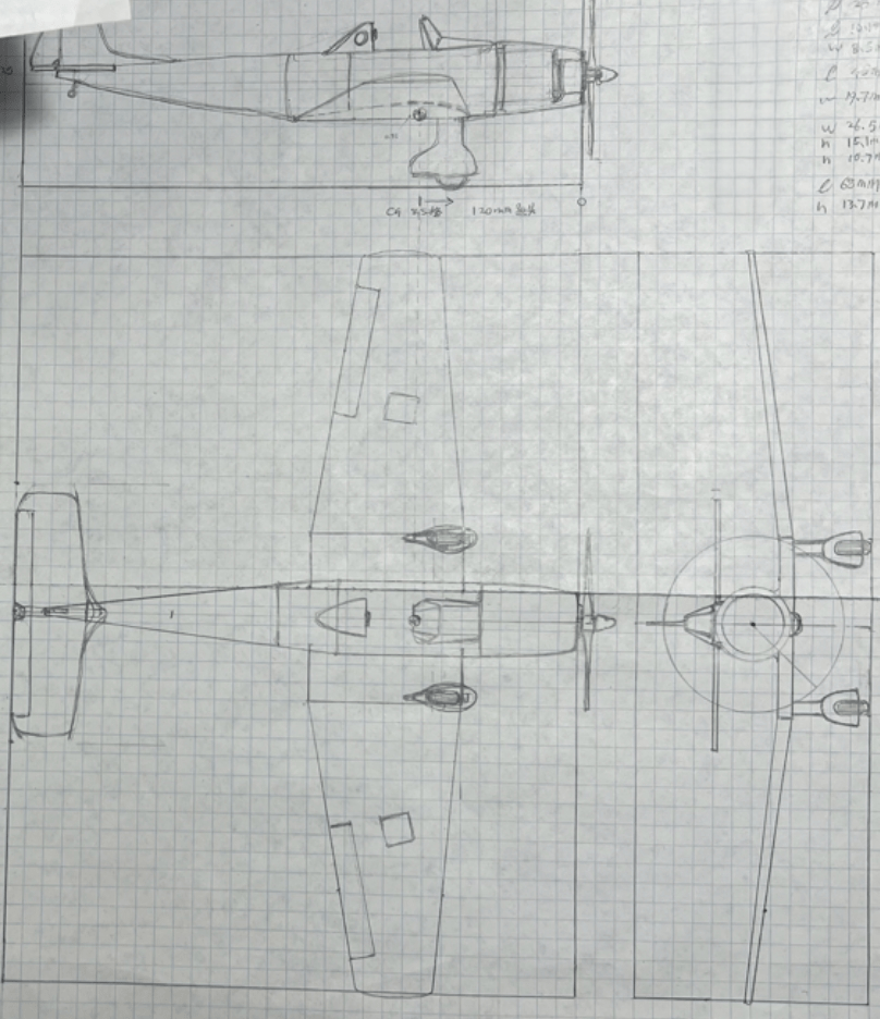
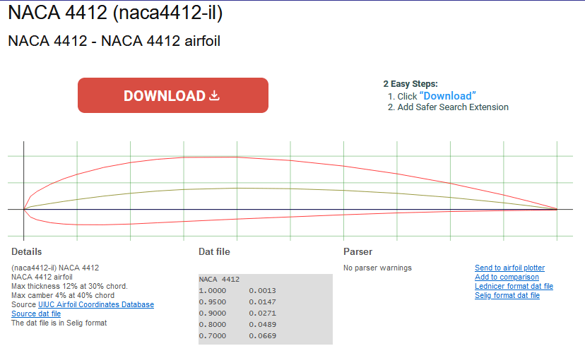
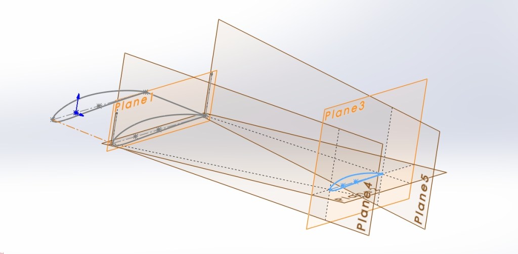
For this design, NACA 4412 airfoil was chosen as this airfoil, as an asymmetrical airfoil, it produces more lift and less drag than symmetrical ones under the same conditions. Most importantly, they can produce lift with zero attack angle! The design does not aim to fly upside down, and the thrust-weight ratio was estimated to be 0.9 which is high enough for the normal performance. The airfoil curve was later downloaded into the Excel sheet for SolidWorks CAD.
The thrust line offset was set to be around 2 degrees to the right to counter-react the left torque rolling tendency. Thus, during the take-off, the rudder’s adjustment is no longer necessary for that effect.
CG location was set to be 1/4 of the chord length from the wing’s leading edge and the CG balancing/mass distribution was calculated in the Excel tool I built which takes the mass and location of each individual component and gives an output of the CG location.
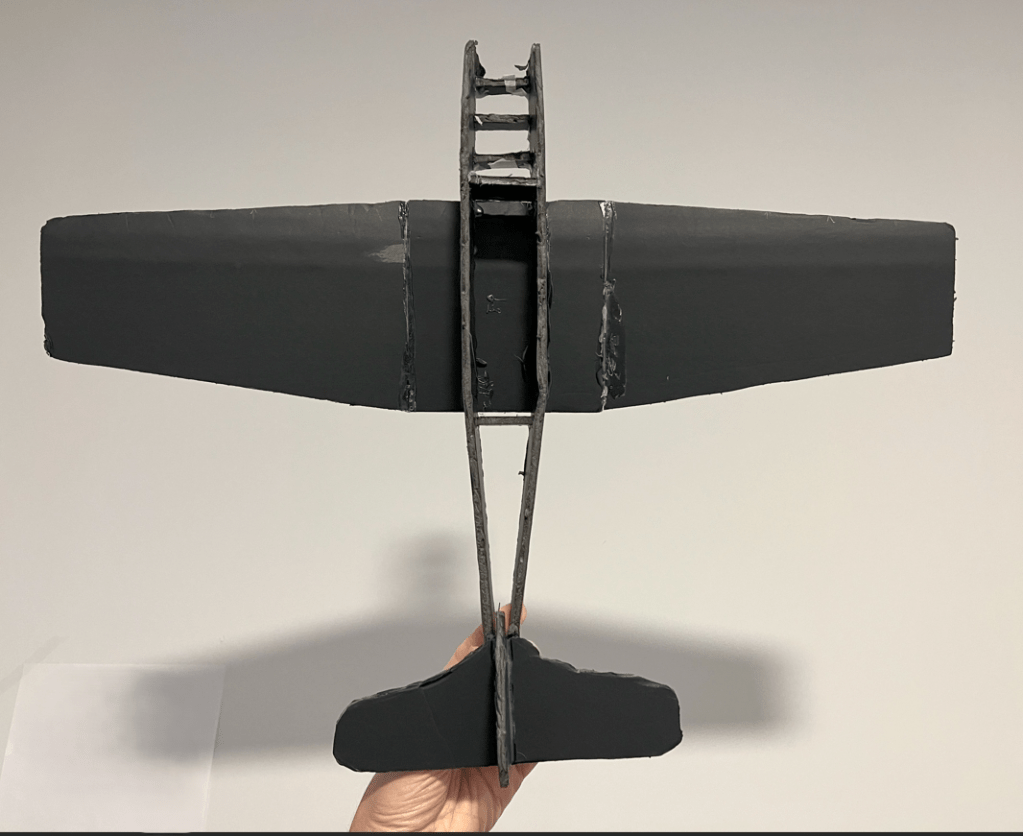
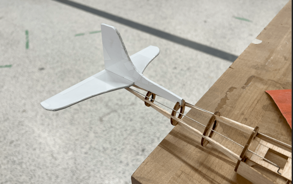
Next step, I built a quick prototype using foam board to varify, evaluate and estimate the realistic stability, fuselage capacity, weight, and CG location.
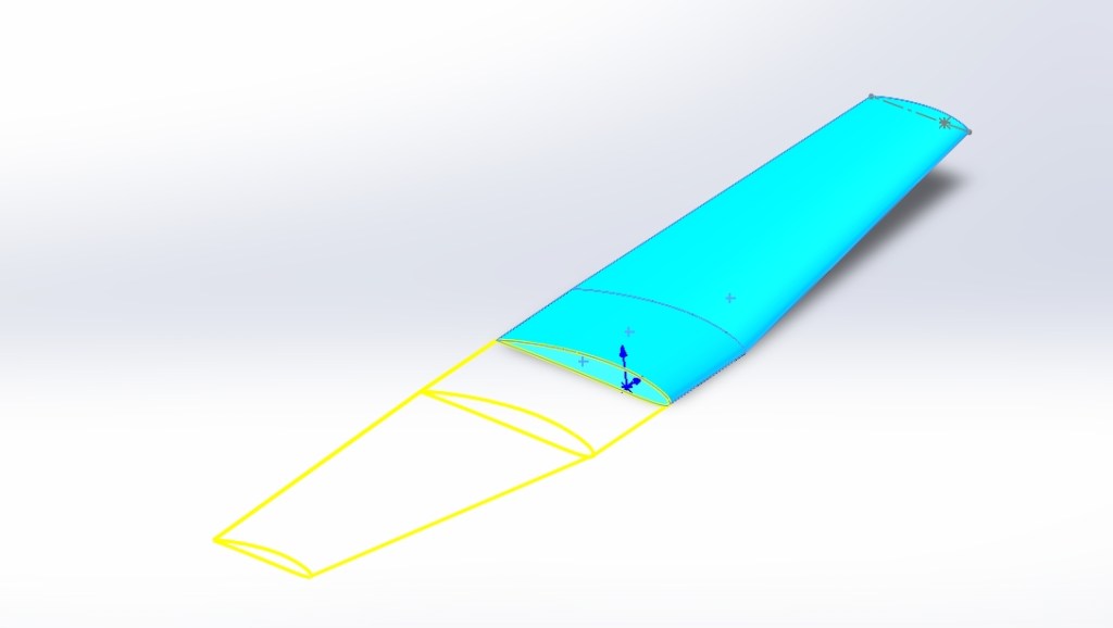
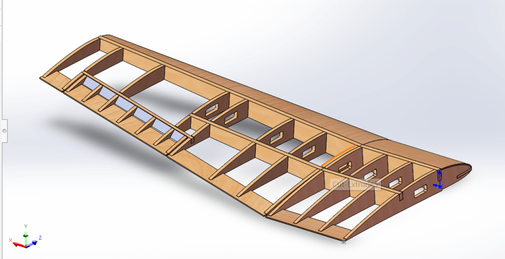
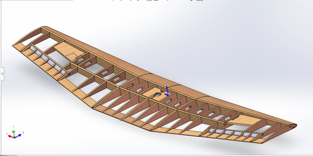
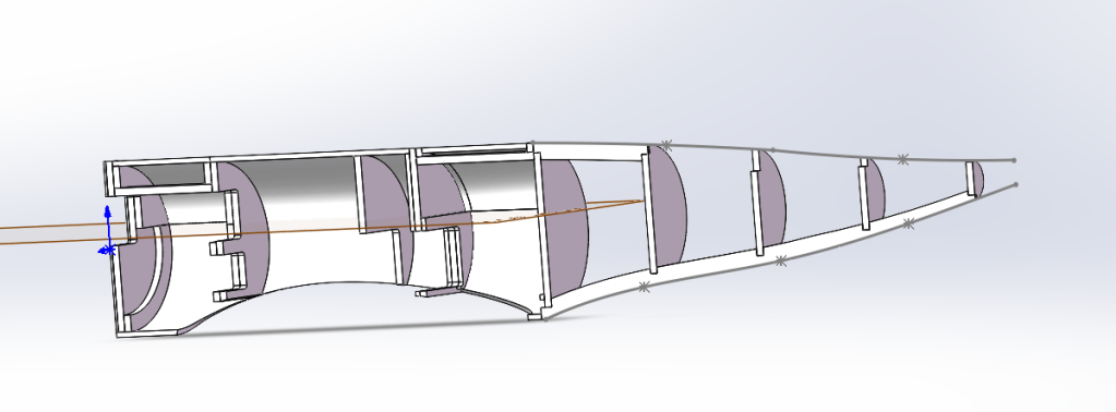
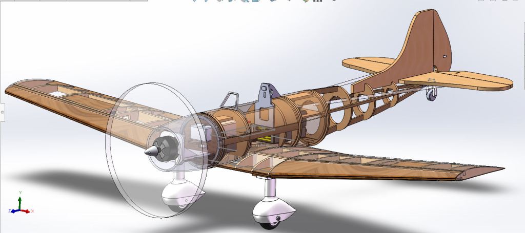
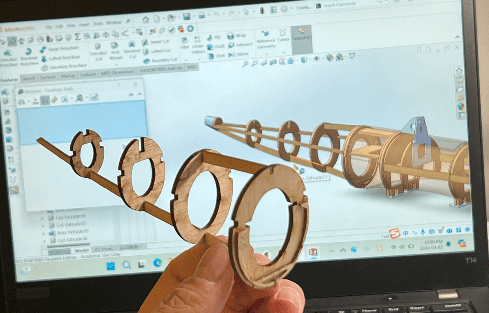
It finally moved to CAD after all the early-stage R&D and validation were done. All the parts and assemblies CAD were done inside the SolidWorks Started with the wing.
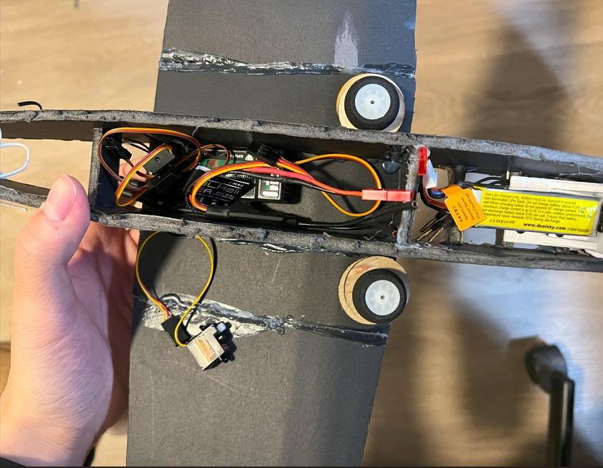
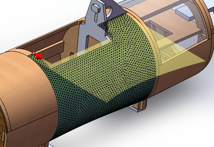
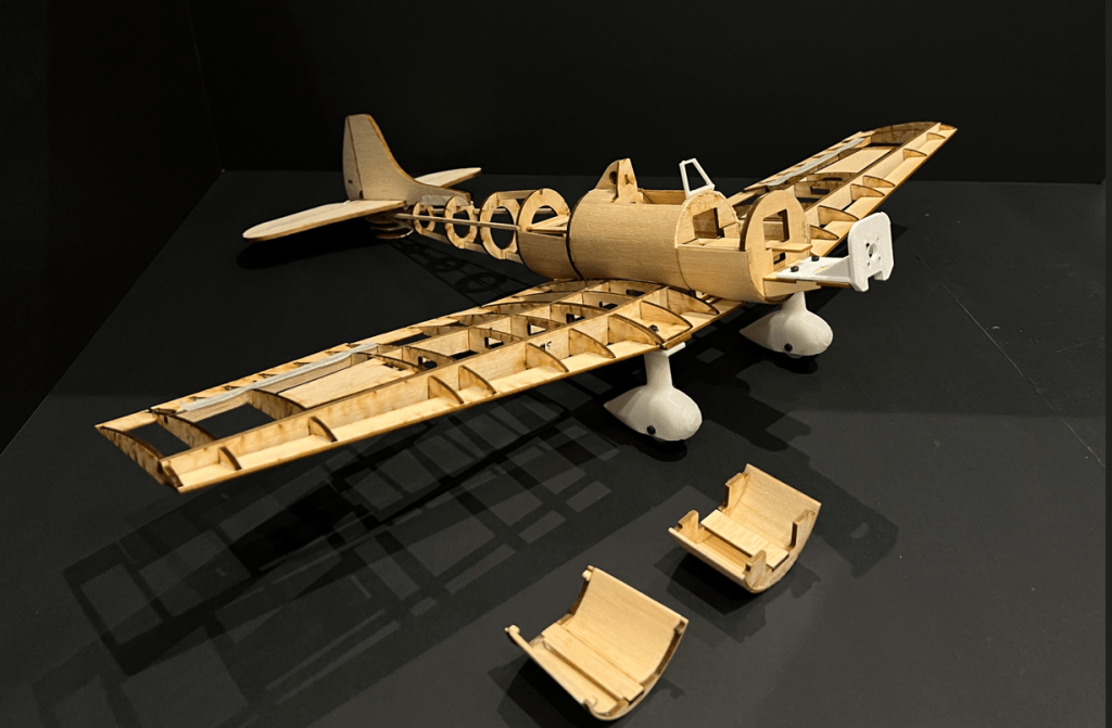
After the finish of the wing’s CAD, we moved to the fuselage detailed design in CAD. However, before that, I had to determine the specific locations/layout for batteries, servos, receivers, wiring, etc. Since the plane is small, the fuselage is very packed, and where to put which component needs to be considered carefully. Moreover, each individual component has to be accessible for later maintenance and replacement (Picture down below).

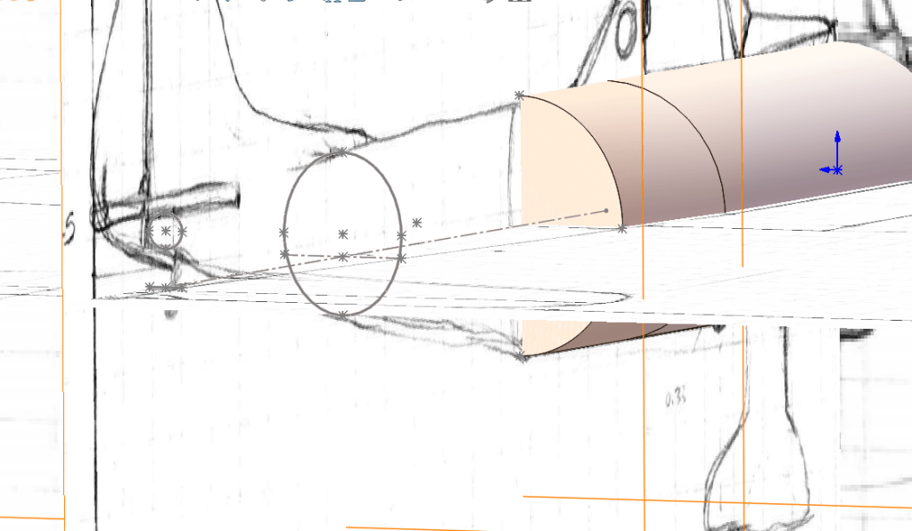
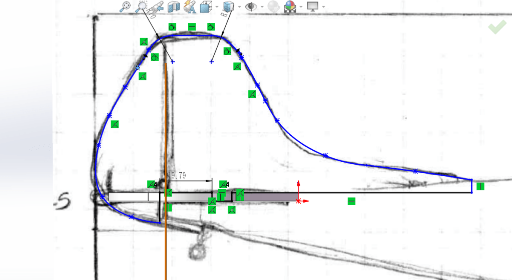
Fuselage CAD started after this… With the dimensions set earlier and the help of the sketch picture feature in SolidWorks, the fuselage could be accurately CADed.

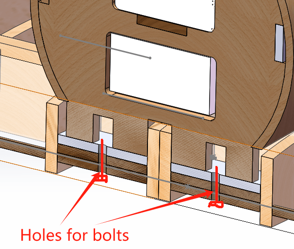
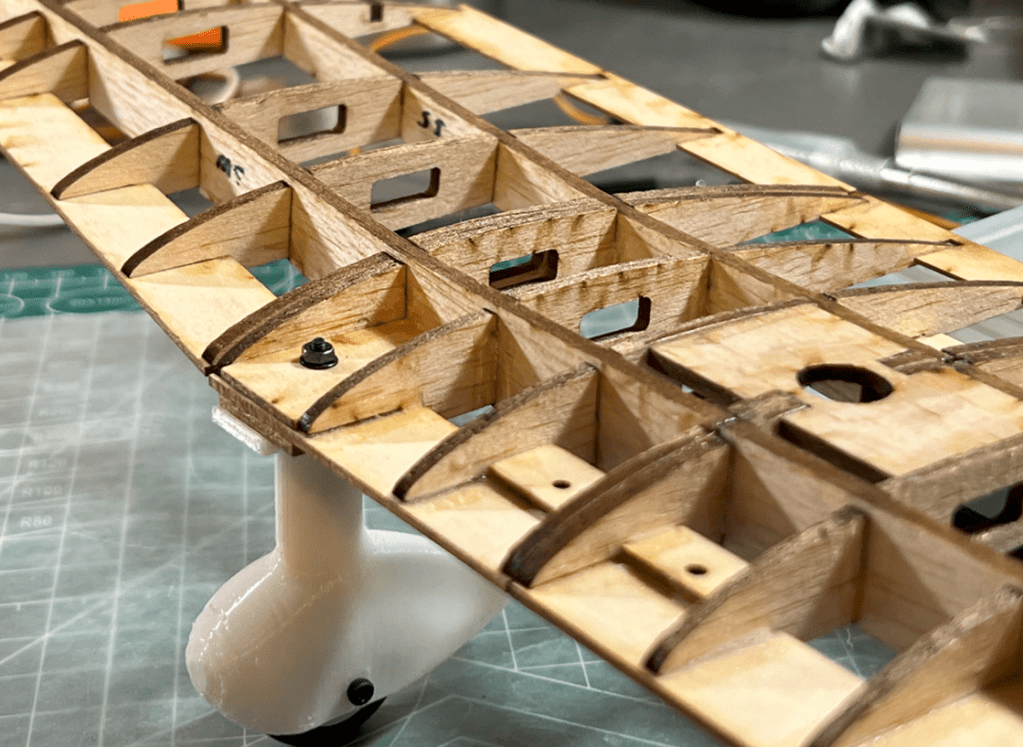
The design for installation is worth mentioning for this design. The wing was designed to be installed with 4 M2 bolt mounting on the strongest structure of the fuselage. the front landing gears were mounted on the leading edge with only 1 M2 bolt and 3D printed structure and base to align accurately and lock firmly. Both connected wooden structures used bass wood which has higher stiffness and strength than balsa.

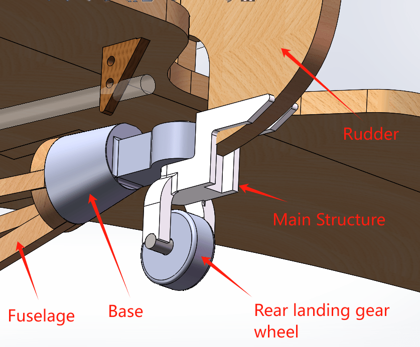
The rear landing gear base was mounted on the end of the fuselage, to synchronize the control of the rudder and the rear landing gear (the rudder has less effect than the rear landing gear on the ground for turning during taxiing), the rear landing gear main structure has a “fork” shape which can be mounted on the rubber to achieve the synchronization.
All the hatch doors and cowling were installed using neodymium magnets since they can provide strong pull force which will secure all the hatches during the flight and they can make taking hatches off easy. As a small plane, the masses of the hatches are neglectable compared to larger aircraft, and fasteners such as bolts and PT screws are more likely to destroy the structure and over-complicate the design.


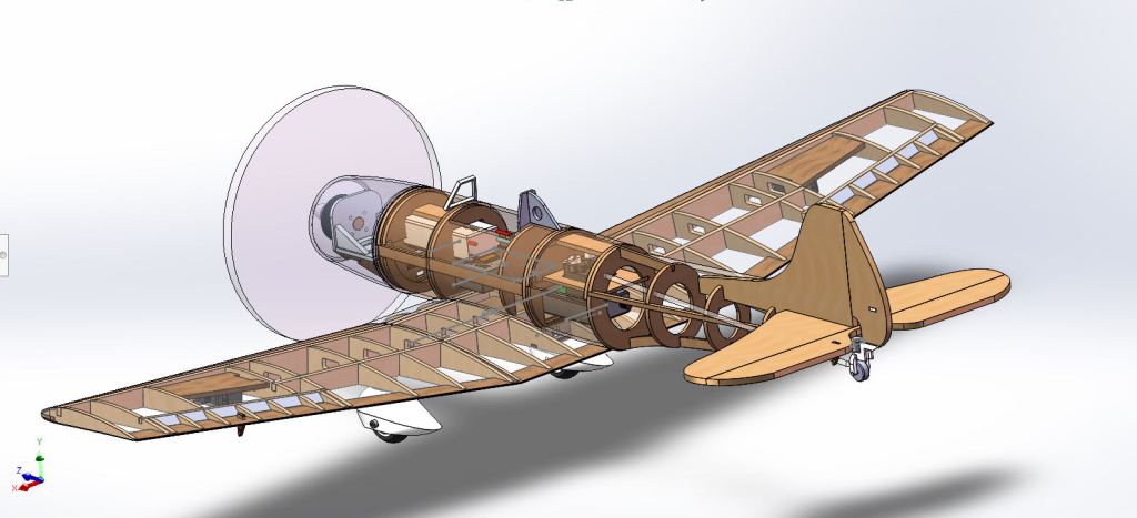
The whole aircraft assembly was finished then…
Build
Shortly after the whole aircraft design was done, “manufacturing” started…
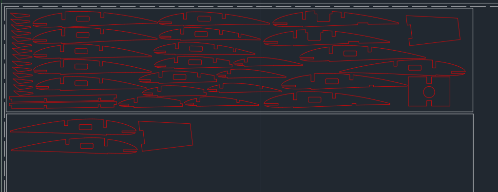
All the wooden components were cut using the laser cutting machine. The structure of the previous design was exported as DXF files to make the laser-cutting template in AutoCAD. AutoCAD made it easy to create neat and packed templates which can save as much material as possible!

Next: Assemble the whole aircraft!
Here, I used CA glue since it can form a strong bond between wood and dries fast. For most of the parts, medium CA glue was applied to fill the gap better while saving more time than thick glue.

Curved wooden surfaces were first cut as flat pieces (flattened the surface in SolidWorks), and applied water to soften the wood then. To make a permanent curved shape, a heat gun was used to quickly dry the wood and lock the shape.

The rest of the attachments such as the front/rear landing gears, cowling, motor mounts, etc. were 3d printed using PLA.

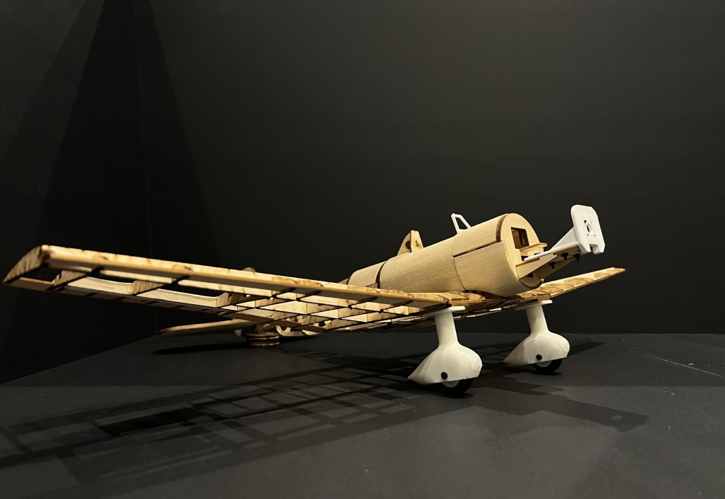
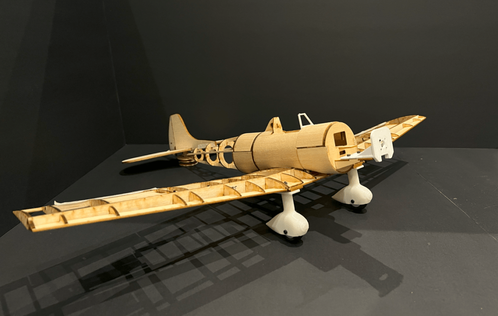
Overall Structure assembly:
The skin of the aircraft used monokote which is a heat-shrink material and is commonly used for most RC balsa planes. Both the heat gun and iron were used to make sure the monokote stuck to the wooden structure well.

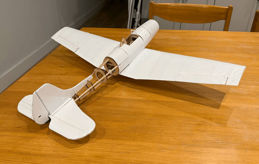
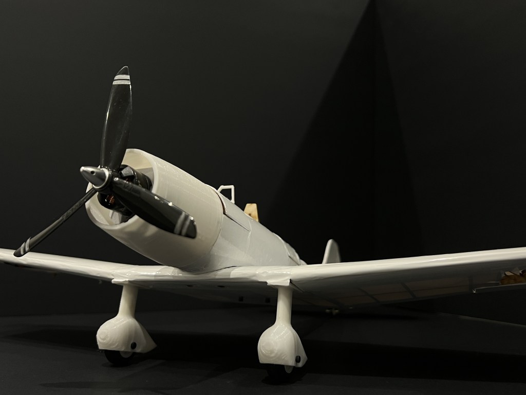
THE FINAL ASSEMBLY:


Flight Test
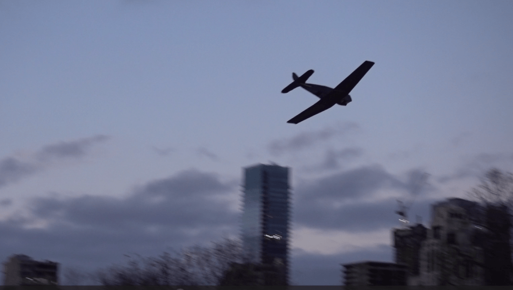
It took off from the ground (conventional take-off), and it flew without any assist from gyro stabilizers.
However…