How simple and reliable the new design can be?
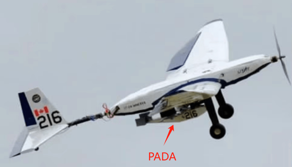
In 2023, our UTAT (University of Toronto Aerospace Team) SAE design team joined the SAE competition and in 2023’s rule, there would be a PADA (Powered Autonomous Delivery Aircraft) being dropped in midair. Specifically, our structure subteam had to work with the fuselage design/redesign.
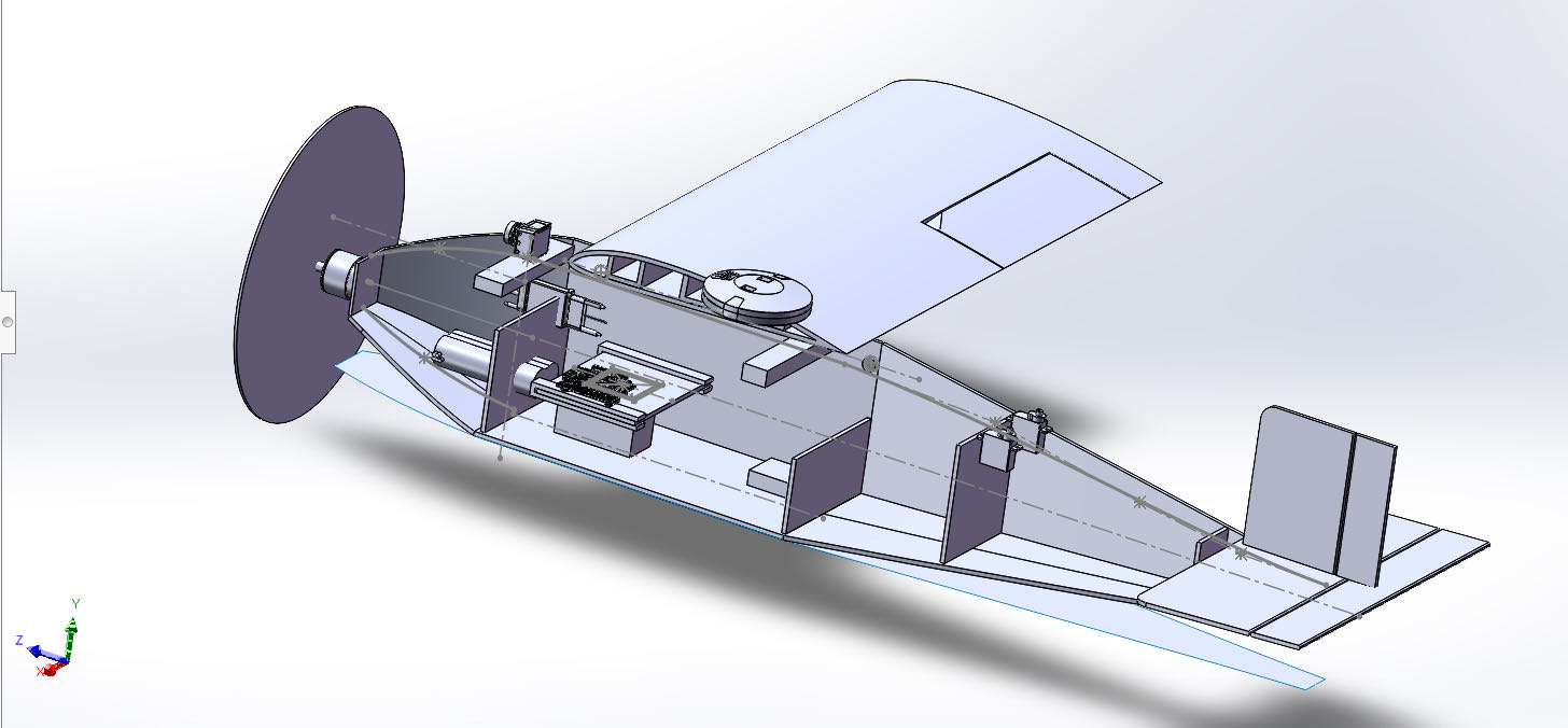
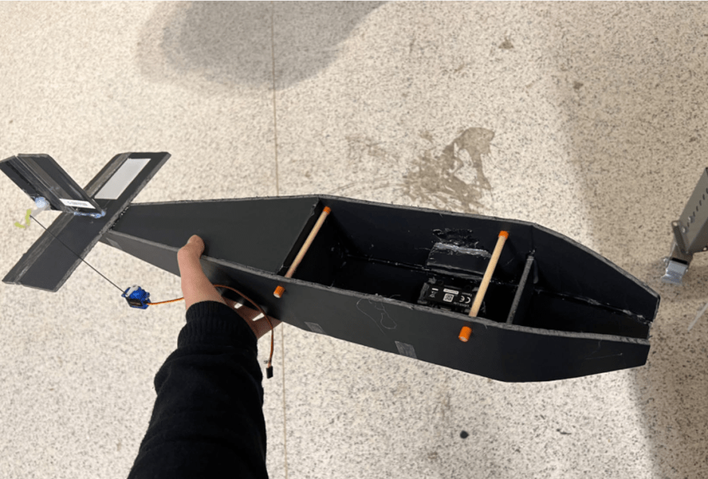
Back then (before I became the structure subteam lead) I was assigned to redesign the Prototype PADA’s fuselage to increase the fuselage capacity and most importantly: fix the LiDAR and Pixracer flight controller in the fuselage to minimize the vibration/displacement during the flight. Most importantly, the design has to be simple so that accessing them would be easy for maintenance
Design
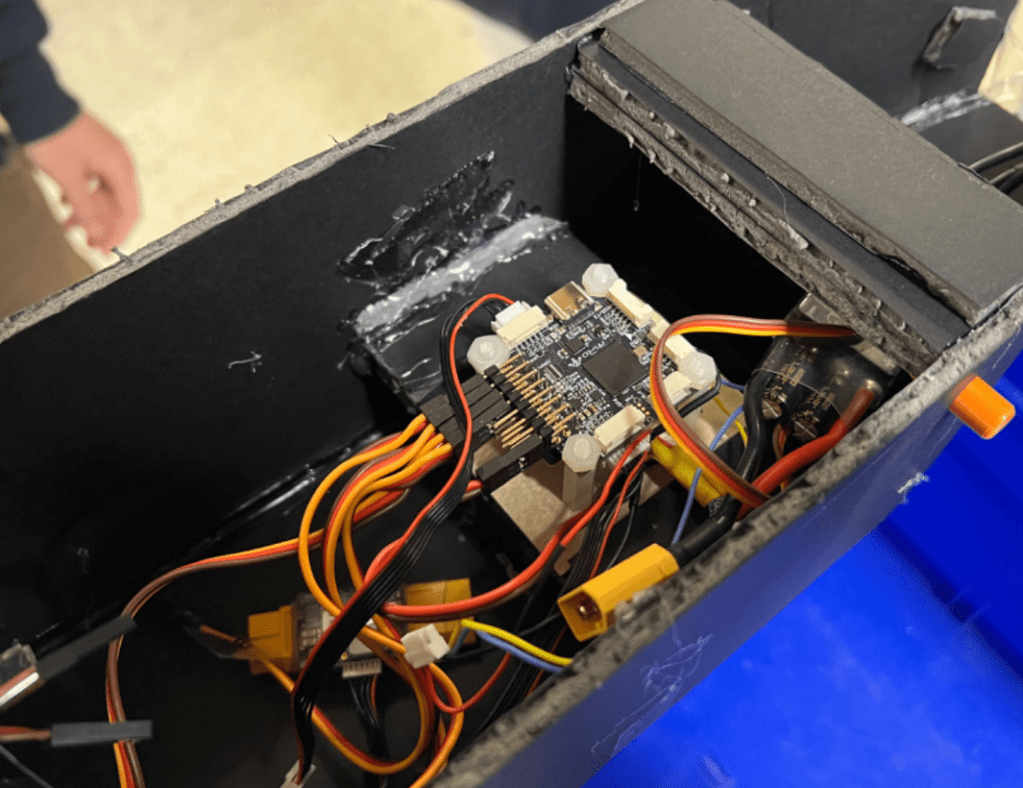
Since the prototype uses foam board which could bearly take bearing stress, it would be very difficult to apply fasteners such as bolts and PT screws without proper inserts. However, foam board is deformable and elastic. Thus, interference fit between foam boards became the best idea at that time. This solution also brought another benefit which is making the contact between the flight controller and the foam body more secure which can further minimize the vibration.
Before the actual design, the CG location had to be rechecked since the fuselage layout was different with many components relocated. It would be a potential problem later if the CG was not located at the ideal location (This would result in flight instability and even crush). The evaluation was done in Excel which took the mass and location of each individual component to calculate the overall CG of the plane, and we needed to ensure the CG location fell into the CG margin which was calculated by the Aerodynamics team.

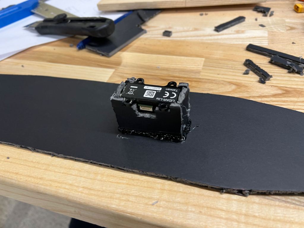
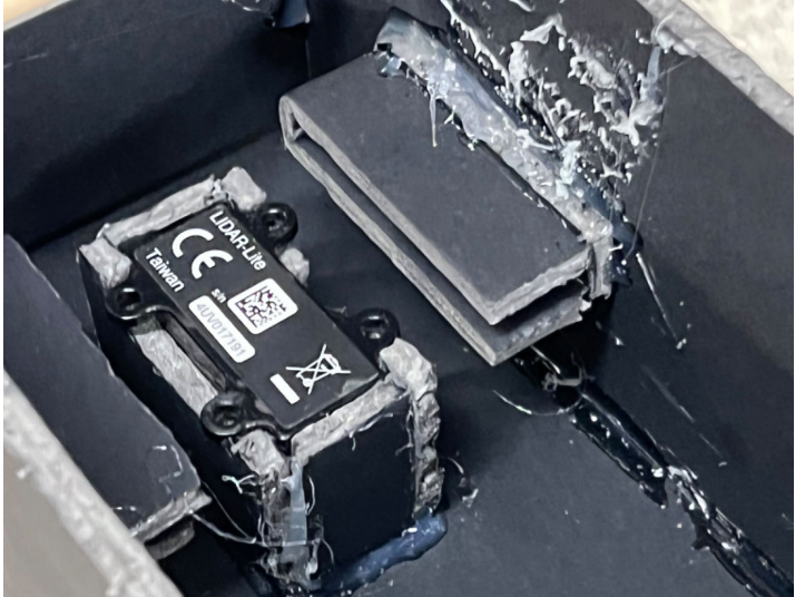
The idea was to first mount the LiDAR on the bottom of the fuselage to scan the ground, and then on top of it, the flight controller could be mounted acting as a “lid” to secure both itself and the LiDAR in position. Generally, the interference fit of the foam board will generate enough friction to hold them in place.
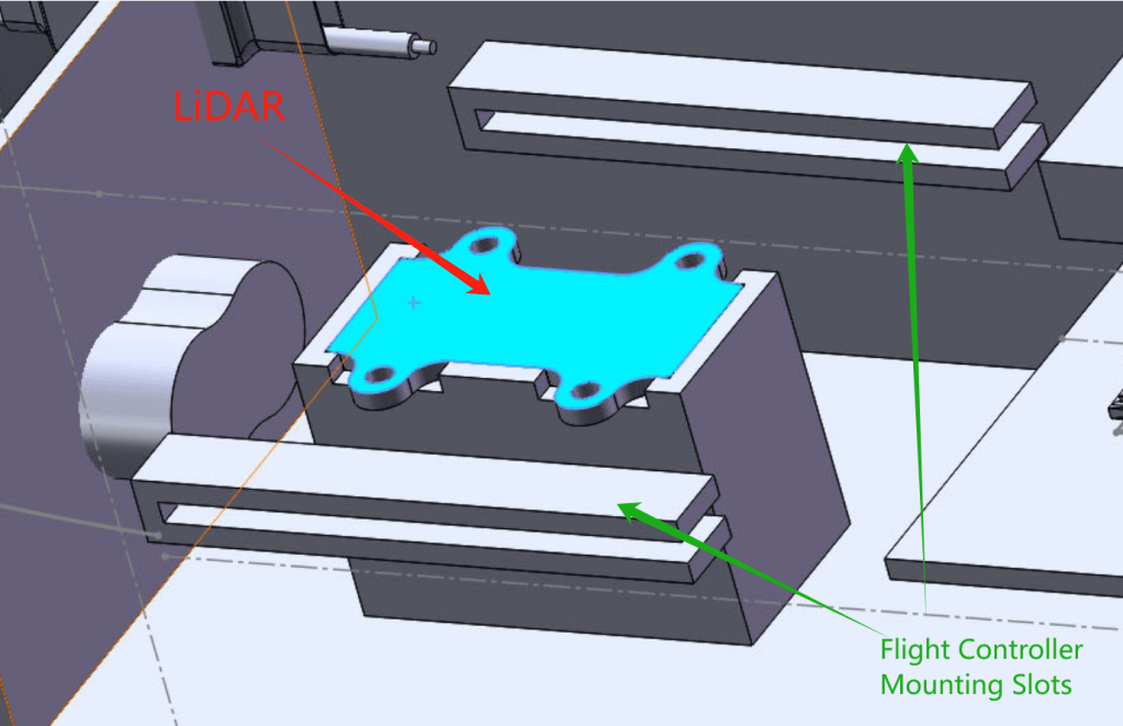
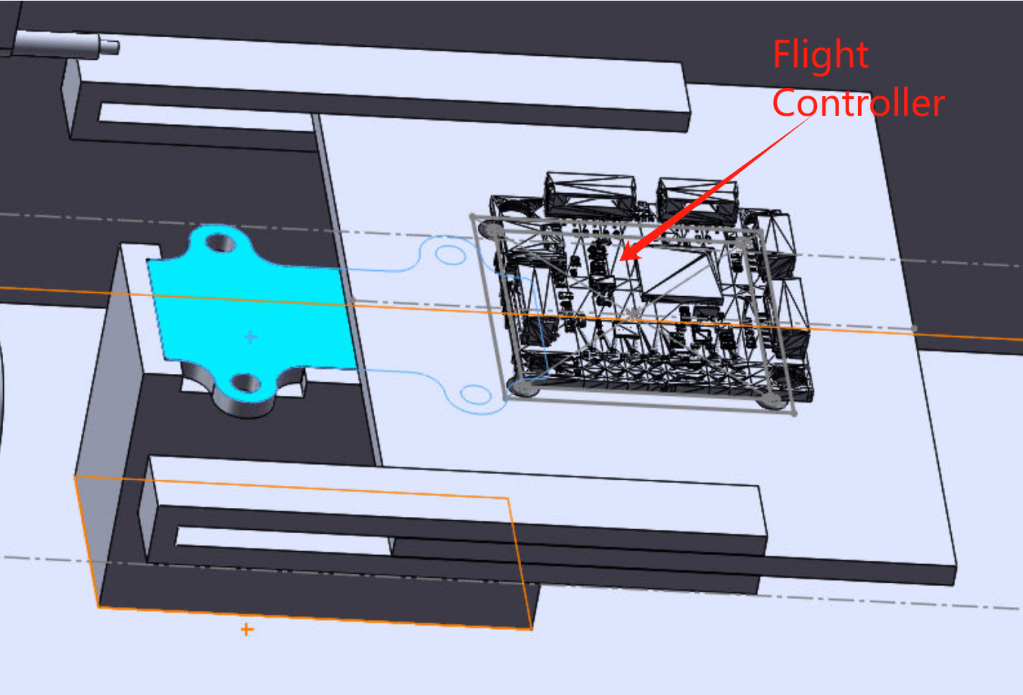
The direction of removing the flight controller was designed to face the tail. This is because considering the worst scenario which is a crash, the inertia would bring everything inside the fuselage forward which can possibly destroy the wiring and the flight controller itself. Therefore, the installation direction was a key concern in the design too.
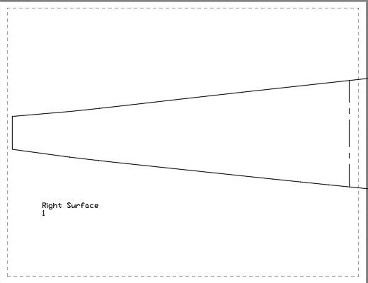
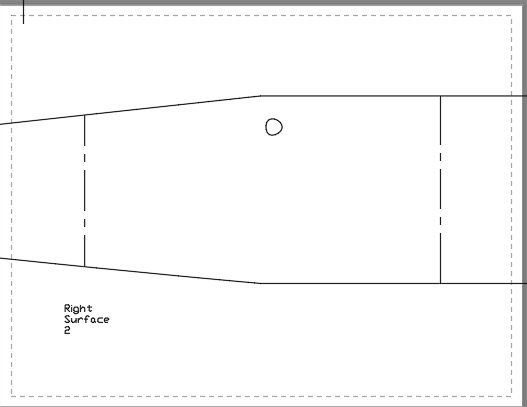
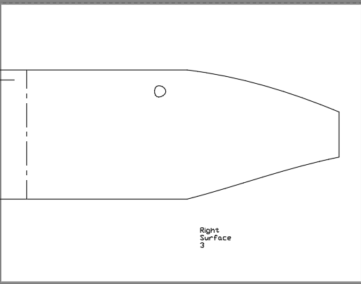
It was completely designed in Solidworks (also the fuselage), and then I used AutoCAD to generate the building plan by printing out the cutting outline to guarantee that the plane could be built accurately.
Build
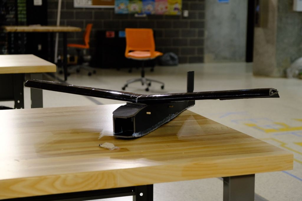
After all the design and preparation were finished, we moved to “manufacturing”!
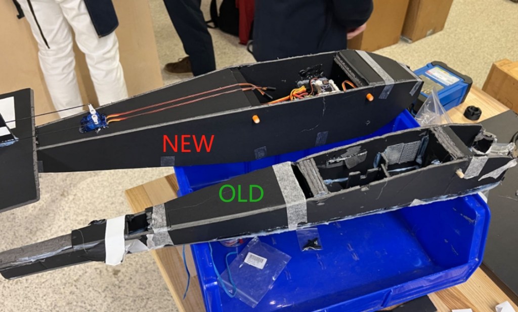
Although the actual product did not look as perfect as the SolidWorks CAD (with “a little bit more” hot glue), The design objectives were all achieved.
Result
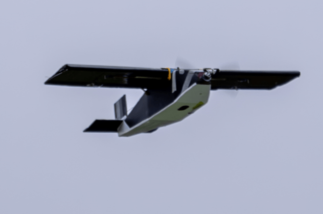
As a result, the design demonstrated great stability as expected, and did not cause any issues during the flight test. It recorded perfect data from the flight tests!
